Wednesday, January 9, 2013

Postscript and PDF Conversions 101

Convert any PDF (or Postscript) to Gerber, GDSII, NC, and more!

Learn how to accurately convert your PDF files (and Postscript) to various EDA/manufacturing formats no one thought was possible.  You now have the freedom to use any graphics software tool (like Adobe Illustrator) to layout unique electronic designs, save them as a PDF (or Postscript), and have our tools ACE 3000 or FAB 3000 accurately convert them to Gerber, GDSII, NC, and more; compatible with any PCB Fabricator or Mask shop.  Also, provides an excellent documentation solution for PCB manufacturers who prefer Fab Drawings in Gerber format instead of PDF (simply convert the PDF drawings to Gerber).
To get started, please perform the following 4 Steps:

STEP 1:  Get your Free Trial of FAB 3000 or ACE 3000.

It's easy. If you haven't purchase FAB 3000 or ACE 3000 yet, get your free trial by clicking the link below and filling out the form:
ACE Translator 3000 V7 - FREE TRIAL
FAB 3000 V6 - FREE TRIAL

STEP 2:  Ghostscript Setup

One of the key components to making Postscript & PDF import work is Ghostscript, an excellent & freely available Postscript interpreter. Our software relies on Ghostscript to read and handle all vector objects such as text, lines, polygons, circles, arcs, splines, and more; however it will not process embedded raster images. Due to the nature of the Ghostscript GPL license, it must be installed separately by the end-user.  Requiring the user to separately install Ghostscript does pose a potential problem, so we've created quick instructions to help you get Ghostscript installed correctly.
1.  There are many, many versions of Ghostscript which can be downloaded and it's updated about every month or two. 
2.  Some installations contain "source code only", some are linux binaries, some are Windows binaries, some are 32-bit binaries and some are 64-bit.
3.  Some versions of Ghostscript produce better results than others (especially for text). For example, if you're getting undesired results for the text (such as wrong font used, or it looks extremely weird), then we strongly encourage you to use a different version of Ghostscript during import; as each major version of Ghostscript seems to handle fonts differently.
So which version of Ghostscript should you choose?
Luckily both FAB and ACE can handle multiple versions of Ghostscript simultaneously during import, so the answer is ALL 3 major releases of Ghostscript:

Ghostscript Version 7
Ghostscript Version 8
Ghostscript Version 9
Note: Click each link above and install all three major versions (if possible).

STEP 3:  Choosing the Best Ghostscript Version to Use during Postscript & PDF import.

Our software easily detects all installations of Ghostscript on your local computer, and lets you choose which version you wish to use during import. Typically all versions of Ghostscript will produce the same results, except for the following:
Text: If you're getting undesired results for the text (such as wrong font used, or it looks extremely weird), then we strongly encourage you use a different version of Ghostscript.  Each major version of Ghostscript handles fonts differently.
 PDF Import: While Ghostscript version 7 works wonderfully for Postscript, it's ability to open many modern PDF files leaves a little to be desired.  If you need to import PDF files, then we recommend a much more updated Ghostscript version such as 8 or newer.  It's okay to have more than one version of Ghostscript on your computer, and many advanced users will instruct our software to use a specific version of Ghostscript when importing Postscript and a different version when importing PDF files.
Helpful Tip: Postscript > PDF.  Postscript files are the preferred file format (over PDF) for converting artworks that require high accuracy. Why? Many well known PDF distillers and other PDF generation tools typically output PDF's with limited resolutions.
We recommend starting with the latest Ghostscript Version 9, and only move down if you're having problems. To choose the Ghostscript version to use during import select the available Ghostscript installations from the pull-down control (see below for a screen capture in ACE 3000):
 

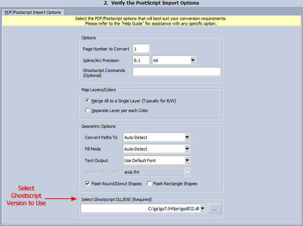
 STEP 4:  Understanding the Postscript/PDF Import Options

Page Number to convert:  Our tools can only import one page at a time, so if your Postscript or PDF file has more than one page, you may choose which page to import. The default is Page 1.
Spline/Arc Precision: The maximum error allowed when computing points on curve. This feature allows designs with large and small curves to equally maintain high-resolution and quality. The smaller the Spline Deviation the more accurate your final curves will become - however exported file sizes may become larger.
Ghostscript Commands (Optional): Request additional commands that will be sent directly to the GhostScript interpreter.
Map Layers/Colors: Determine how to associate postscript objects to a layer.
Merge All to a Single Layer: Place all postscript objects onto a single layer.
Separate Layer per each Color: This setting creates a new layer for each object color in the postscript file.
Convert Paths To: Determine how to process Path objects.
Auto-Detect: Use the same path types found in the Postscript/PDF.
Polygon: Output all paths as polygons.
Rounded: Force all paths to be rounded. Sometimes when using Postscript/PDF's for artwork you'll discover that the path quality is not very good (especially for PCB's), so a rounded path produces better results.
Truncate: Output all paths as truncated paths (square path with no end cap).
Extended: Output all paths as extended paths (square path with 1/2 width end cap).
Fill Mode: Determine how to fill objects.
Auto-Detect: In most Postscript drawings objects drawn with a "white" color represent a hole (or transparency). This setting will De-Embed all postscript objects that are the color "white" from all remaining objects.
De-Embed: Use built-in De-Embed Algorithm to determine what is transparent.
Fill All: Fill all objects and ignore transparency.
No Fill: When possible, do not fill any objects.
Text Output: Determine how to process Text objects.
None: Ignore Text
Polygon: Output Text as Polygons (default).
Polygon Adjustable: Output Text as Polygons with Adjustable spacing.
Use Default Font: Substitute Postscript font with an ACE font. This may be necessary when the font quality from Ghostscript is poor.
Default Font: ACE/FAB 3000 font to use when Text Output is set to "Use Default Font".
Flash Round/Donut Shapes: This option will detect circles & donut shapes and convert them to gerber flashes. Very useful when exporting to Gerber
Flash Rectangle Shapes: This option will detect square & rectangular shapes and convert them to gerber flashes. Very useful when exporting to Gerber
Select Ghostscript DLL/EXE: To import Postscript / PDF requires that Ghostscript is installed. You can choose which Ghostscript version to use during import, and you may also use the file selector '...' to manually assign a specific version of Ghostscript.


TUTORIAL MOVIE:  See Postscript/PDF Import in Action

Using ACE 3000 to import Postscript using Ghostscript 7 which provides bad Text, so repeat using Ghostscript 9. See how easy it is to choose which Ghostscript Version to use.
http://www.youtube.com/watch?v=kV95mQ-Zs2g&feature=player_embedded


Using FAB 3000, import a PDF file of Fab Drawing and export to Gerber:
http://www.youtube.com/watch?v=voIlnDGtlJg&feature=player_embedded


 TROUBLE SHOOTING:
It's very common for us to receive a support email or message...
I want to import a Postscript/PDF file into ACE 3000, it gets to 15% and then says:
FATAL: Unable to parse Postscript/PDF file:
FATAL: Verify if the Ghostscript interpreter is installed correctly.
FATAL: Translation Failed.

Can you please help me?


1. Make sure you have the latest version of our software tools. 
Why?  We're continuously improving our software and have made many improvements on how it finds and links to Ghostscript.  Chances are if you're using an older version pre-November 2012, it may be the problem.

2. Make sure you tell our software where to find Ghostscript.
Why?  Typically our software will first search the System Registry for the Ghostscript DLL, however many systems & installations are setup different; so relying on our tools to find Ghostscript can cause inconsistencies.  Your best bet (before performing the Postscript/PDF Import), is to start our software and assign the Ghostscript DLL location:
3.  Make sure you have installed the 32-bit version of Ghostscript and not the 64-bit Ghostscript. 
Why? Even though you may have a 64-bit computer, our software uses the 32-bit version of Ghostscript.  Thus the 64-bit version of Ghostscript will not work.

4.  Try selecting the Ghostscript command-line executable instead of the DLL. 
Why?  Our software can handle both the DLL and EXE version of Ghostscript.  In some cases, the EXE works better than the DLL.  Go to the menu:  Setup | Options...   Go to the tab "Misc." and enter the location of the "Ghostscript DLL".
ex.  C:\gs\gs7.05\bin\gsdll32.exe

5. Try using of Environment Variable "PS". 
Why?  When our software still cannot find Ghostscript, it will search for the environment variable:  PS   All you do is go to the Windows System Settings, press button Advanced and add the "Environment Variable". 

Note:  Don't forget you need to restart your computer for the system variable to take effect.


Note:  Both FAB 3000 and ACE 3000 will work with just about any version of Ghostscript, however we have spent the most time testing 7.05, 8.53, and the new version 9.

DXF Conversion Secrets for Gerber, GDS-II, ODB++, etc.

By Simon Garrison, Applications Manager - Numerical Innovations

It is estimated over 10%-15% of all electronic layouts (for PCB's, RF, IC/MEMs, etc) are still designed using Mechanical CAD tools (like AutoCAD, SolidWorks, ProE, etc). Why?

The power of MCAD tools (like AutoCAD) are that they support a wide array of entities types which can be used to easily construct electronic designs from the simplest PCB to the most complex IC/MEMs circuit.  Designers generally choose to layout their designs in MCAD when existing EDA/Layout tools do not possess the capabilities to meet unique geometrical requirements.  Once the layout is completed and a DXF file is outputted; they will attempt to convert to a manufacturing format (such as Gerber data, GDS-II, ODB++, NC, etc.)  – seems simple enough right? Wrong! This approach usually results in an astonished look on the designers face, when they view their converted manufacturing files and discover those files are not worthy of sending out for fabrication... Why?

This has been a mystery which has plagued designers and mask makers for well over 20 years, and the purpose of this article is to help explain common problems and how to solve them.
FACT: Most Fabricators & Mask shops won’t touch your DXF data with a 10 foot pole and ask that you provide them only with the manufacturing formats (such as Gerber data, GDS-II, ODB++, NC, etc.) – which is probably why you are reading this article in the first place :)

1. Understand the file format basics:

DXF/DWG Format :
DXF stands for Drawing Exchange Format, and it is a format for transferring drawings between Computer Aided Design systems. DXF is widely used as the de facto standard in the engineering and construction industries. The DXF format is a tagged data representation of all the information contained in an AutoCAD® drawing file. Tagged data means that each data element in the file is preceded by an integer number that is called a group code. A group code's value indicates what type of data element follows. This value also indicates the meaning of a data element for a given object (or record) type. Virtually all user-specified information in a drawing file can be represented in DXF format. DWG is essentially a binary version of DXF which tends to be smaller and cause less parsing errors during conversions.
Gerber Format :
To figure out the problems and how to overcome them, first lets look that the format you want to convert your AutoCAD drawing to: Gerber. The Gerber format is well over 35 years old and is simply an ASCII text file containing X,Y coordinates, and shapes (i.e apertures/dcodes). For more information about Gerber, visit the following link: http://www.numericalinnovations.com/pages/gerber-format
GDS-II Format:
GDSII is a binary file format created in the 1970's which is classified as a "data interchange format", used for transferring mask-design data between the IC designer and the fabrication facility.  GDS-II can only support simple physical objects such as Polygons, Paths, Rectangles, and Instances (for hierarchy). FACT: Unlike the older Gerber and GDSII formats, every year you can expect there’s going to be a new release of AutoCAD and with each release there are usually changes to the entity types, DXF format, which continuously pose compatibility issues and other problems.
ODB++ Format:
ODB++ is the most intelligent PCB data exchange format available today, capturing all CAD/EDA, assembly and PCB fabrication knowledge in one single, unified database. Originally developed by Valor Computerized Systems for use in its own PCB CAD/CAM systems, Genesis 2000, Enterprise 3000 and Trilogy , ODB++ has already become widely accepted as the de facto industry standard, providing unprecedented power to PCB design, fabrication and assembly, with the flexibility to expand as required. In parallel, ODB++ is providing most of the technological basis for the new IPC2581 standard for data exchange in the PCB fabrication and assembly industry.

2. When possible, keep your Drawings simple (Using 5 Fundamental Entities)

The easiest way to convert DXF to manufacturing formats (such as Gerber data, GDS-II, ODB++, NC) is to keep things simple. DXF files support hundreds of various entity types (like Hatches, Blocks/Inserts, 3D objects, Tapered Polylines, TrueType fonts & Multiline-text, Splines, Regions, plus Model/Paper Space considerations, and much more), so the question remains how do we convert those fancy entity types into simple manufacturing formats which only contains X,Y coordinates, and shapes – Simple, for best results create your layouts using the 5 fundamental DXF entities that will lead to successful conversions.
What are the 5 fundamental DXF entities?
Polylines (or LW Polylines), Circles, Text, Blocks, Inserts. Believe or not, you can create just about any PCB/RF layout using only these 5 entities, and they most closely represent objects in Manufacturing data.
Polylines (or LW Polylines): A series of connected lines and arcs than may have varying widths. This is the most common entity used to construct a PCB/RF layout and is used in about 80% of the layout. Polylines with width are used to draw traces (i.e. tracks) to connect pads. Polylines with 0-width are commonly used to create filled boundaries. Polylines may also be used to created square and donut pads.

Circles: Most commonly used to draw round pads.
Text: Used to draw silkscreen and labels. Typically using stick fonts which are AutoCAD compiled fonts (SHX) provide the best results, and are output as trace segments in manufacturing data. TrueType fonts are acceptable provided your conversion tool can output them as simple polygons.
Blocks / Inserts: Typically used to create a hierarchy in your design, and provide an optimized method to add repeated entities into your drawing. Blocks are essentially individual drawings that are inserted into a parent drawing. During the insertion, blocks can be rotated, scaled, and transformed in any direction. Blocks can be inserted multiple times as and array using Minsert (Multiple Inserts) which allows an array of blocks either rectangular or polar.

3. Understand how to Fill Boundaries generated from MCAD

A filled boundary in manufacturing formats (such as Gerber, GDS-II, ODB++) typically represents areas where metal will be present. Most MCAD tools (like AutoCAD) do not support filled boundaries and instead only display object outlines or wire-frame. 
FACT: The most common reason Designers have problems when converting their DXF to manufacturing formats (such as Gerber, GDS-II, ODB++) is directly tied to the fact MCAD tools typically do not display filled boundaries correctly -- thus a Designer must visualize how their layout will be filled -- even though their MCAD tools is displaying outlines & wire-frames only.

How do I create a filled area in my Manufacturing data?
To create a filled area, first draw a closed, continuous boundary (with 0-width polyline) that does not self-intersect. Remember manufacturing formats (such as Gerber, GDS-II, ODB++) have stringent fill rules: All boundaries must be continuous, with no overlapping or self-intersections (like a bow-tie). The direction is typically not significant for filled boundaries (i.e clockwise or counter-clockwise).
Using JOIN:  The Boundaries in my Manufacturing data are still not filled, why?
Most likely your boundaries are not closed & continuous (as described above). In many cases you may have a drawing which consists of individual line and arc segments – which are not continuous. We recommend that you convert those boundaries to Closed, 0-width polylines using the command “Pedit” and then select “Join”.  We offer two conversion tools: FAB 3000 and ACE 3000 which have built in join tools that instantly connect all adjacent lines/arcs and convert them to closed boundaries.  See movie tutorial "FAB 3000: Using Join and DeEmbed"


4. Understand COMPOSITE Fill. Determine what areas should be Dark or Clear (i.e. Island).

To understand composites, we first recommend checking out an article from the ACE 3000 help manual called Composites 101

Depending on the manufacturing format you're outputting to composites will be handled different.
Gerber / ODB++ Format: In the Gerber and ODB++ format, there is no such thing as island/hole detection. Fortunately both formats directly support Composites which allow you to explicitly define what to make clear or dark using the gerber commands “LPD” (Layer Polarity Dark) and “LPC” (Layer Polarity Clear). The most reliable way to define a composite, is to create separate DXF layers for each polarity change. For example: If you require a dark rectangular boundary with many clear holes, you should create two layers:
One layer which contains only the rectangular boundary, and a second layer which only contains the holes. During DXF conversion you can create a composite gerber merge and assign the polarity for each layer.
GDS-II Format: GDS-II doesn't support Composites (Dark/Clear), it only supports simple Polygons/Rects/Paths, so you must use a boolean engine to add "cutlines" that connect inner holes with outer boundaries.
What is Polygon De-Embedding?

Some conversion tools will have a featured called “Polygon De-Embedding”, where the conversion tool will decipher which objects are contained inside of other objects and logically try to determine what should be an island or hole and then explicitly output that information to the manufacturing format file.
Should I use Solid Hatch to composite fill an area?
Solid hatches look good in AutoCAD because they are the one of few entities in AutoCAD that appeared filled (on the AutoCAD screen). But remember a solid hatch is drawn on top of your existing drawing, causing duplicate data in the DXF, and results from a Gerber conversion can be messy because of the duplicate objects. If you must use solid hatches, please make sure your conversion software supports solid hatching and has the ability to detect islands/holes when necessary.


Tutorial Demonstrations using ACE 3000, FAB 3000, and EasyGerb

 Using ACE Translator 3000 to convert DXF to Gerber, GDSII, and more.

DXF to Gerber, GDSII, and more. Converting DXF to Gerber (for a microwave coil)
http://www.youtube.com/watch?v=ev94IaLu0ek
http://www.youtube.com/watch?v=f-Wpv4kW06Y

Using FAB 3000 to convert DXF

Easily Convert DXF to Gerber
FAB 3000: Import DXF, use join and export to gerber
http://www.youtube.com/watch?feature=player_embedded&v=1e1igE30nlw
http://www.youtube.com/watch?feature=player_embedded&v=pW4TyMKtnUU

Use EasyGerb to output Gerber files, while directly inside AutoCAD

 
Using EasyGerb 5 Inside AutoCAD to export Gerber files. Generate Composite Layers using EasyGerb
http://www.youtube.com/watch?feature=player_embedded&v=qQVM7arXIvs
http://www.youtube.com/watch?feature=player_embedded&v=ooKU7E21lyo


Checkout the User Forum for more assistance and answers to frequently asked questions about DXF conversions and more.

 ACE Translator Forum: http://forums.numericalinnovations.com/?forum=106289

FAB 3000 Forum: http://forums.numericalinnovations.com/?forum=106290
EasyGerb Forum: http://forums.numericalinnovations.com/?forum=106292


Have more questions? Feel free to contact us directly: support@numericalinnovations.com
http://www.numericalinnovations.com

Sunday, October 16, 2011

PCB West Exhibition 2011 - Santa Clara, CA

This year, Numerical Innovations, attended the PCB West Conference that was held September 27 - 29, 2011 at the Santa Clara Convention Center.

The exhibit floor was open for one day only - Wednesday the 28th, with lots of activity at our booth.

Simon was in full demonstration mode with DFM Now! our featured product,showing many of the Engineers and Designers how DFM Now! works. While both Steve and I worked the floor, talking to and answering questions from everyone who stopped by.

We had a pretty amazing day, re-connecting with the PCB Industry and had a lot of fun doing what we do best!

Thank you to everyone who made it a success and a big shout-out to the crew at UP Media for a great show, see you next year at PCB West 2012!


Wednesday, September 14, 2011

Give Value First, Don't Add It!

By Miranda Yip
Sales Manager - Numerical Innovations


Why do your customers choose your product or services? Is it because you're cheaper than Companies A & B? Or, because you can do the job faster? Both options are taken into consideration, but both are not the final reasons why you're chosen for the job.

The bottom line is - your product and services are seen as valuable stepping stones needed to take, in order to help your customers business become more
productive and successful.

Give Value First, Don't add it!

Make this your Motto and Mission Statement. It is super important to stop thinking about what's in it for me and start by thinking about what's best for your customer.

Remember, Value is not something you add-on! Value is something done for the customer, in favor of the customer. (Jeffrey Gitomer)

To become recognized as a business of Value you must give first! Here at Numerical Innovations, our example of Value is DFM Now!

DFM Now! is a tool for both Engineers and Designers to use, that ensures their Gerber's and Drill files are correct - Prior to manufacturing.

With DFM Now! every user is able to run a DFM Check, Extract & Compare Nets, Copper Area Calculation, send instant RFQ and more. All of this, for free.

The next time you're face to face with a potential new customer, jump right in and give Value first. Offer helpful advice and ask key questions to find out what their goals are and what they really wish to accomplish by using your product or services.

By giving Value first, you will become recognized as a valuable and resourceful place of business. You will find that your customers will like you, trust you, buy from you and even recommend you to their friends.

Don't wait for your customer to ask for help, Beat them to the punch and give Value first - Don't Add it!


Tuesday, August 9, 2011

OEM/Custom Software, helping your company reach a finished product!


Summer has almost come to an end and for most of us and it's back to the desk and drawing board. Today, I've picked a pretty hidden topic and service we provide that not so many may know about: OEM/Custom Software!

What is OEM/Custom Software?
Well OEM stands for "Original Equipment Manufacturer"and OEM Software is a phrase that refers to software that is sold to Companies in large quantities, for the purpose of bundling with computer software/hardware. One of the reasons a company request OEM/Custom Software to be built in the first place, is because there is a particular job that needs to be done and specialized software is required to specifically suit the companies needs - More of a tailored fit, so to speak. Sometimes small and large companies need more than what's readily available in retail software packages.

And that's where we step in and work our magic!

Project Types
We can handle anything you throw at us, but here's a glimpse at some of the work we specialize in:
* CAD Translators - Let us build a custom DLL or library which will allows your existing software tool to import or export any CAD format.
* PCB Design Tool - Perfect for PCB Fabricators who wish to offer their customers more value than just boards.
* Layout Visualization Tools - Add a powerful visual interface into your software tool.
* DFM Solution - Need a solution that detects potential problems in a Design/Layout before sending out to manufacturing?
* CAD/CAM Controller - Does your company create a Laser cutter, Inkjet Printer, or other device that could benefit from increased opportunities in the electronics industry. And so Much More.
The options listed above gives you an idea of what we are capable of and more. If you need something else, just ask us - we're here to help you!

OEM vs In-house
In most cases, the cost to build OEM/Custom software from scratch can be quite costly. But here's where it get's even better, We've already written 70% of the code your company needs. This enables us to offer robust solutions for a fraction of the cost & time; when compared to your company developing them in-house.

Customer List
Here are a few Companies who have chosen us to provide specialized software to assist them with their work.
* FUJIFILM: We developed an OEM version of ACE 3000 for their Dimatix printer with a custom bitmap output to meet FUJIFILM's advanced requirements. FUJIFILM can now handle ODB++, Gerber, DWG, DXF, GDSII and output directly to their Dimatix printers; opening the door for increased opportunities in the electronics industry.
* Schmid & Partner Engineering AG: We built a custom DLL allowing SEMCAD X to import Gerber, ODB++, and GDSII files; allowing SEMCAD X to now perform complex simulation for EMC/EMI testing on various electronic circuits.
* Anaren Microwave: We built a vital AutoCAD ARX conversion utility used everyday by their engineering staff . And More.

Tips to Consider
So now that I've go you thinking about OEM/Custom Software – So now what?
Here are a few helpful pointers to think about before requesting OEM/Custom Software:
* What is my Project Type? (see above)
* Do I have a set Time-frame for purchasing your OEM Custom Software?
* Is this for commercial or in-house use?
* How many license do I need?
* What is my Companies Budget?

Remember, by giving us as much information possible, will help us with providing your company the solution you need to reach your finished product.

Our code is of the highest quality and has been employed in many products and solutions used by thousands of companies around the world and we look forward to working with you.

If you're ready to submit a Request for OEM/Custom Software, use the link below to tell us all about it:
http://www.numericalinnovations.com/oem.html

Cheers,

Miranda Yip
Sales Manager
sales@numericalinnovations.com

Thursday, July 28, 2011

4 Key Rules for Next-Generation Advertising

By Miranda Yip
Sales Manager - Numerical Innovations


1. Target & Exposure

Before we jump right into the deep end ask yourself this: Am I targeting the right people? Is my Target audience connecting with the marketing material I'm using? Am I providing a solution to help fix a major problem?
If you've answered Yes, Yes & Yes - Great!

The next step then is simple, Exposure, Exposure, Exposure and do this at least 7 x times!!

Although it may not be cast in stone, the truth is you can't just depend on a single marketing strategy and be done with it. You have to keep pressing on and pursuing your target audience at least 7 x times by placing yourself in front of them, before it really sinks in and captures the audiences attention.

2. Information Overload

Firstly to get a message across to any human being is a process. The mind is bombarded with thousands of commercials & advertising campaigns every single day, that your audience has put up a wall and grown thick skin and learn to ignore the overload of information and noise.

The secret here is to STAND out and lead with a solution to their problems, keep your name and brand in sight at all times and repeat this 7 x times! Just like the old saying goes "Out of Sight, Out of Mind." Don't fall into this trap.

3. Prove the Value

Next, it must always be remembered that in these tough economic times, price is a very big player in the game of advertising. But the truth behind the line "I'm not sure if I need this" just means, the prospect has not been sold on the value behind the service or product being offered. But, I'm sure if you could provide 7 x valuable reasons, why there was a need for what's offered, there wouldn't be a problem finding the money to pay.

That's why it's crucial to keep advertising. Keep your name and brand in sight at all times, so that money isn't a concern because the value has already been proven.

4. Trust

So now that you've cut through all the noise and proven why there's a need for your product or service, comes the hardest wall of all to get over. Prospects have to like you and trust you in order to buy from you!

The reality is, it takes time for people to get to know you. Once they know you, they need time to get to like you and your business. Once they trust you and you've provided value - only then will they be ready to buy.

Saturday, June 18, 2011

DFM Now! - A “Win-Win” situation for both the PCB Designer and Manufacturer


By Simon Garrison, Numerical Innovations (a Division of Caneberra Technologies, Inc.)


We have recently introduced a new product called DFM Now!, which is targeted to help facilitate the ordering process between the PCB Designer and Manufacturer. The two biggest road blocks in the PCB Ordering process are when the Gerber files (provided by the designer) contain any "show stoppers" (i.e. DFM or Net errors which prevent the manufacturer from making the board ), and the time required by the PCB Manufacturer to extract all of the necessary information from the gerber files to accurately quote the manufacturing cost for the board.

DFM Now! is a one-of-a-kind product with a unique new concept: Put all that Power in the hands of the PCB designer - absolutely Free!

Truthfully speaking, PCB designers want to be sure they are sending good data to PCB manufacturers, they just need to know how and then be provided with the correct tools to get the job done as stated below: "I figure it's my responsibility anyway to provide correct gerbers, and not depend on outsiders to check my work." - Garry Motter, Engineering Manager at SciMeasure Analytical Systems, Inc.

With DFM Now! PCB designers can analyze their Gerber files for fabrication and netlist issues beforehand, to prevent scrap and revision spins. For companies with security restrictions, there is no worry about having to send over their valuable designs to outsiders via the internet and wait for the DFM results; they can now simply perform all the checks securely on their
own desktop. In addition, DFM Now! extracts all of the critical design information needed, so quotations can be quickly created by the PCB manufacturer.

Time is Money... and many PCB Designs can take hundreds of hours to complete from start-to-finish. Why not take an additional 20 minutes to thoroughly check your Gerbers with DFM Now! before sending to manufacturing? DFM Now! results in a “Win-Win” situation for both the PCB Designer and Manufacturer. It can be downloaded free of charge at http://www.dfmnow.com

DFM Now! is completely independent and not aligned with any one PCB manufacturer, so there is no hidden push to force designers to use a specific manufacturer. DFM Now! was designed to be an open market system for the PCB industry, so any company may advertise inside DFM Now! free of charge. For more information about advertising in DFM Now! visit, http://www.numericalinnovations.com/dfmnow_signup.html